At Demag, we talk a lot about overhead cranes and hoists. It’s what we’re known best for. As a crane service technician, you’re called out to diagnose and maintain Demag motors on lifting equipment. Sometimes though, you arrive on the job and find that it’s a Demag motor attached to an application like a transfer car, bundling equipment, processing equipment, or even a theme park display. Luckily, the adjustment procedures you already use on Demag crane equipment can also be used so you can expertly handle the work.
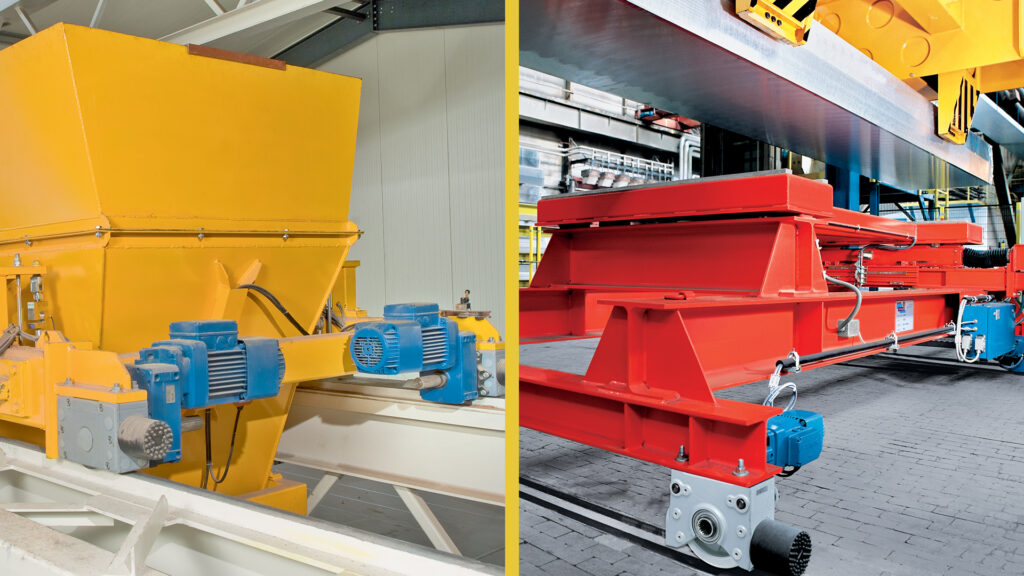
As experts in the material handling space, Demag manufactures overhead lifting equipment and components and systems for use with other material handling equipment. Considered our Drives products, this product offering includes AC induction motors, gearboxes, wheel systems, and complete travel solutions to meet the needs of applications with standard or specialized requirements. Our solutions are specialized for precise positioning and extreme environments. When you’re called out to maintain a Demag motor on any material handling application, you likely have the foundational knowledge for diagnosis and maintenance.
Adjustment and Service of KB Motors
Demag is world famous for its conical profile KB motor. The KB motor was introduced to the North American market in 1984. There are a huge number of these motors in-use today on cranes, hoists and on material handling applications.
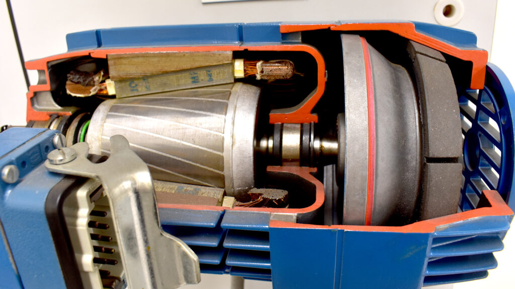
Conical rotor motors have a mechanical brake, meaning the brake release is accomplished by simply energizing the motor to create motion called axial displacement. Turn on power and the rotor and shaft are pulled forward into the stator. This simultaneously releases the holding brake and allows rotation to begin. When power is turned off, the internal brake spring, located on the front end of the rotor, mechanically pushes the rotor, main motor shaft, and brake assembly into the brake cover at the rear of the motor to stop rotation.
Want to understand the concept of axial displacement further? Watch our video on YouTube: https://youtu.be/Es-xdcBcU38
Making a Brake Adjustment on a Demag KB Motor
Checking the brake wear in a conical motor is accomplished by measuring its axial displacement. When the published maximum value for axial displacement is reached, an adjustment is needed to compensate for the brake lining wear.
This adjustment simply moves the disc that carries the rubberized lining (shaped like a ring) closer to the rear brake cover on the motor. A tapered lock nut is mounted to the hub of the carrier disk. The carrier disk must be unbolted and repositioned on the motor shaft, then the bolts retightened. When the grooves on the outer diameter of the rubberized ring wear fully down, the brake ring must be replaced.
Demag KB Motors are found on AF series gearboxes and DH wire rope hoists. We put together a series of videos on the brake adjustment of the main hoist motor on the hoist. These videos will give you a good understanding of the adjustment concept on these motors. https://www.youtube.com/watch?v=PtHlV5oEdgA&list=PLCcB7JxQJEd–F6BHIyM5vc1orUh3xbjc
Adjustment and Service of Demag ZB Motors
Even though conical rotor motors are highly versatile, they may not be ideal for applications that require variable speed. Many times, Demag model ZB cylindrical profile motors are better suited to these applications. The ZB has an electrical d.c. magnet coil to operate the brake and is ideally suited for VFC control.
Making a Brake Adjustment on a Demag ZB Motor
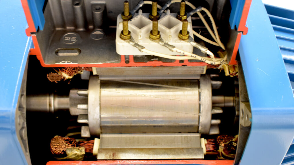
ZB Motors do not use axial displacement to release the brake. It uses an electrical coil called a magnebody (also called a magnet body) which controls the brake. The rubberized lining is on a two-sided brake disk between the coil assembly and the end cap of the motor. Energizing the magnetic coil draws a pressure plate to the magnet to overcome mechanical spring pressure, releasing the brake disc and motor shaft for rotation.
Actuation of the magnebody is controlled by pre-engineered modules that provide brake rectification and optimal switching of the voltage to the coil. Brake voltage can be supplied by the 3-phase motor supply or external control circuits. This is one of the major factors in selecting the proper brake control module.
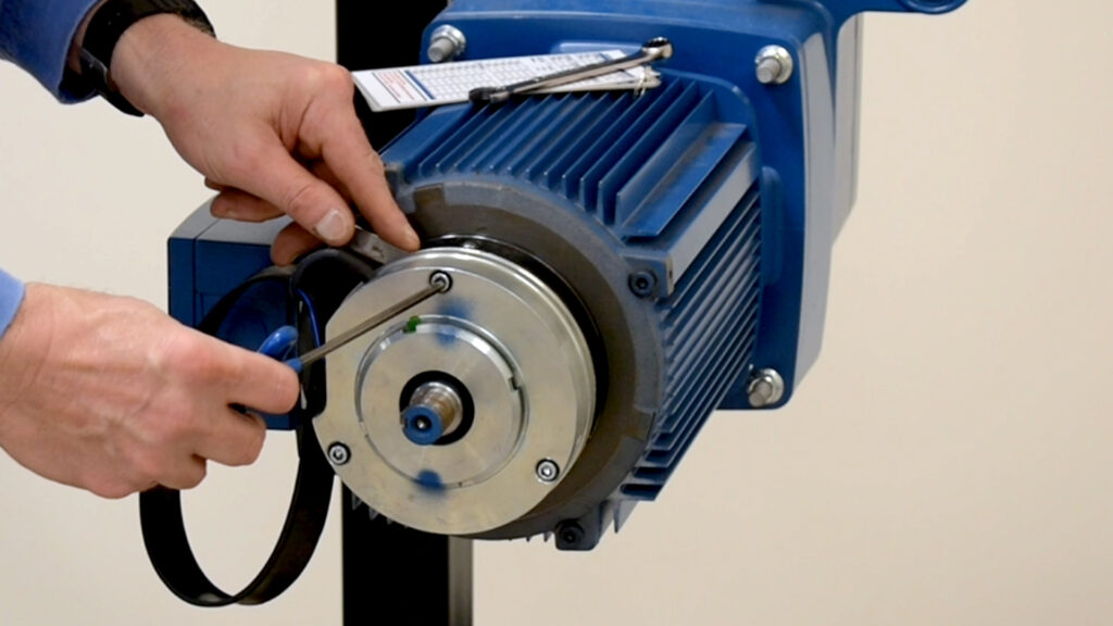
The brake is maintained by measuring the airgap and remaining thickness of the rubberized lining material. This airgap check is made by inserting feeler gauges between the pressure plate and the magnebody. Read about this procedure here: http://blog.demagcranes.com/en-us/how-to-check-crane-brake-adjustments-on-demag-end-trucks-equipped-with-zb-motors/
The airgap should be even and consistent around the entire perimeter of the brake assembly. ZB motors typically have wear indicator marks to specify when the maximum wear point has been reached. Once reached, it is time to replace the brake disc.
Brake Spare Parts for Demag ZB Motors
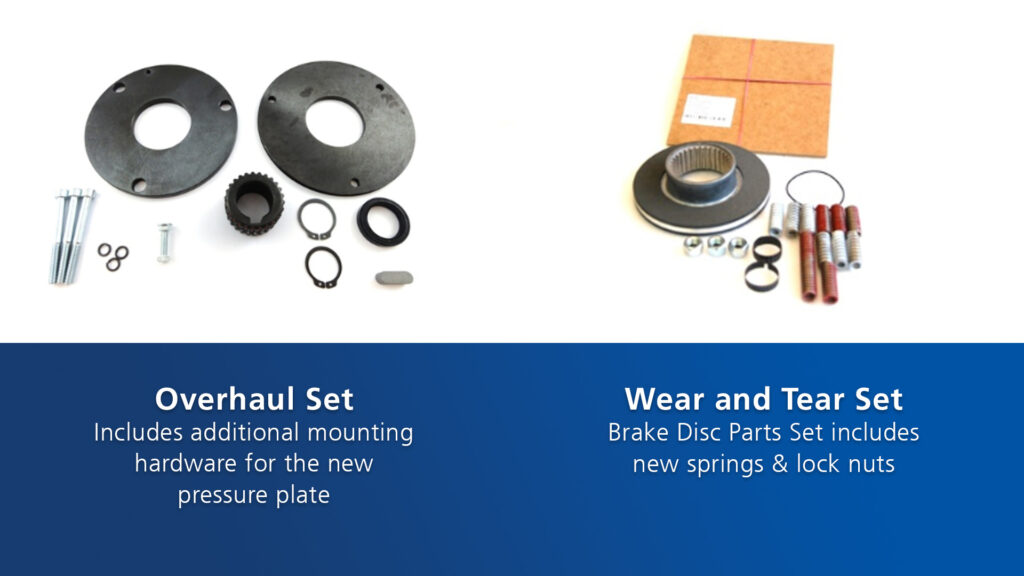
When you determine it’s time to replace parts, contact us or an Authorized Demag Dealer for genuine Demag spare parts. Knowing the brake size is important when ordering parts. It can be determined by a suffix on the model designator preceded by the letter B found on the motor data tag, for example B050 or B280. A new brake disc parts set includes new springs and locknuts, called a Wear and Tear set. An Overhaul Set can be ordered if damage is detected on the pressure plate, which comes with additional mounting hardware.
Magnebodies are sold as separate items. Make sure to look at the small tag attached to the wires that connect the magnebody to the terminals in the motor terminal box. This tag will identify its part number, operating voltage, and ohm value of the coil, also important information for diagnosing when troubleshooting.
Troubleshooting the Motor Windings on ZB Motors
Demag motors are typically built with bi-metallic temperature overload switches inside the windings. These switches will open when normal operating temperatures are exceeded. If the motor is overheating, further investigation and diagnosis is necessary. Read more about the steps to take to check the motor windings. http://blog.demagcranes.com/en-us/troubleshooting-3-phase-ac-motors-on-demag-hoists-trolleys-and-bridge-drives/
Additional Service Tips for Demag Motors
Always keep the cooling fins clean and make general observations that the motors are running smoothly. Keeping a record of in-range airgap measurements, axial displacements, amp draw, and temperature readings will allow you to make comparisons during the motor’s working life. As the internal mechanisms wear with cycle life, these indicators will predict when bearings, internal springs, and cushion packs should be replaced. Demag sells all these parts along with special feeler gauges to setup proper rotor-to-stator airgaps. It is critical to use genuine Demag parts to rebuild motors to maintain proper design tolerances.
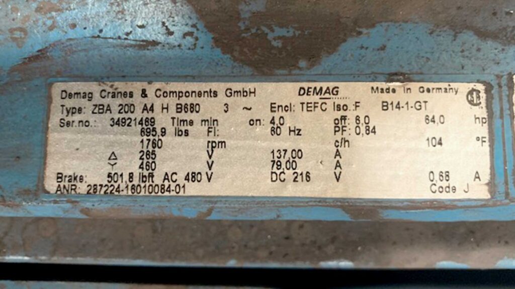
Rated amp draw information is contained on the data plate located in the vicinity of the terminal box. The data plate contains the identification and build data which is useful when determining the correct replacement parts. We recommend taking photos of the data plates and providing these with any parts orders. Serial numbers found on these plates can also help locate fabrication records so any custom features can be readily identified.
You may be used to servicing Demag KB and ZB motors on our cranes and hoists, but they are also found on other material handling solutions. Don’t be apprehensive about servicing motors on non-crane applications. You’re likely familiar with adjustment procedures of these motors found on cranes, but when you do need help, make sure you check the Demag blog and our YouTube channel. You can always reach out to the Demag location nearest you for additional support when conducting the service and maintenance of Demag Drives products.
- Understanding Wire Rope Lay for Your Next Wire Rope Hoist Repair or Inspection - December 21, 2023
- Diagnosing Additional Error Codes on Demag CANBUS Hoists and Cranes - March 28, 2023
- Maintenance and Service Tips for Demag KB and ZB Motors in Non-Crane Applications - February 7, 2023
