If you are a crane service technician called to service a hoist or trolley from the 1990s through 2010 you might find the need to replace the BER brake relay. The BER brake relay is commonly found in the trolley wiring for a Demag DR COM wire rope hoist. Over time the design of the BER timer has been updated and slightly changed so when you go to service a hoist with this timer, you should read this post. In this post, we will give you an overview of the design changes and the process for replacement.
What Does the BER Brake Relay Do?
BER Brake Relays are braking timers that slow the transition between high speed and low speed on 2-speed travel motions. BER is a German acronym assigned to the electrical unit used for control of 2-speed motors that need to be switched down from fast to slow speed in normal use. Activation of low speed is delayed by the BER brake timer, which avoids a sudden change to low speed. Left unchecked, the sudden speed change would create load swing and excessive mechanical loading of components in the travel drives. In conjunction with the timer, the selected motors also have internal flywheels to cushion any speed changes and smooth out operation. When the motor is momentarily deenergized, rpm slows, and mechanical braking begins under the influence of the internal flywheel. The delay time varies per application and can be programmed by setting a dial under the front cover of the BER.
Cranes with Wire Rope Hoists Using the BER Brake Relay
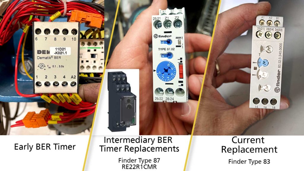
BER brake relays/ BER timers can be found in the control circuits for 2-speed trolleys and bridges from the 1990’s through 2010. They were prominently used on the EKDR-COM wire rope hoist with contactor-controlled, 2 speed trolleys. When a BER requires replacement, you will quickly find out that the original design has been updated and the replacement part is a smaller sized relay with an adjustable built in delay circuit. There have been different brands of BER replacements used over the years. The earliest BER replacements were the Schneider brand RE22R1CMR followed by the Finder Type 87. Today you will find the latest replacement is the Finder Type 83. Some rewiring was necessary for installing a Type 87 and is also required for Type 83 when changing out the old BER timer with the current part.
Replacing the Finder Type 83
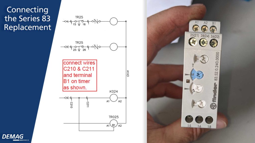
The wiring sketch for connecting the series 83 is provided above. Note that the series 83 does not require the Z1 to Z2 jumper found on a series 87 timer.
Replacing an Early Version BER
The early version BER has different terminal numbers and lacks a constant control power feed connection so replacing this early version has added complications. The crossover for terminal wiring and instruction for adding the power supply wire to the A1 terminal are as follows:
| Old | New |
|---|---|
| 1 | 15 |
| 2 | 16 |
| 3 | 25 |
| 4 | 26 |
| A2 | A2 |
First, take wire C210 on 6 and wire C211 on 7 and join them together at B1 on the new timer. The constant control voltage supply for terminal A1 on the new timer is required and does not exist in original BER version 1 wiring. A new wire needs to be added to connect terminal A1 to the control power circuit in the hoist panel. The control power supply is labelled as A1X1 and is daisy-chained through the panel for other devices like for instance the MKA. This new A1X1 connection can be at a terminal on another device where two wires can fit in or add a terminal splice.
Making the Delay Setting
Newer timers have dials on their face for making the delay setting, but the dials are different in each case. If you can read the old settings, we recommend duplicating those on the replacement.
The typical factory settings for the Finder Type 83 are as follows:
| Dial | Setting |
|---|---|
| Top Dial | 10 Seconds |
| Large Blue Rotary | 15% |
| Third Rotary | Double Flag Symbol |
| Bottom Rotary | EEa |
Use the illustration(s) on the face of the timer to match up the settings. If you have any doubt, please contact Technical Support at Demag for advice.
BER settings are between 0.1 – 3.0 seconds. If the setting time is too short, regenerative braking torque will cause a noticeable jolt in the travel motion. If the programmed delay is too long, travel will come to a complete standstill. The typical factory default setting is 1.5 seconds. Optimum setting is best achieved with some trial and error to “dial it in” to meet your needs.
The BER brake relay commonly found in the trolley wiring for a Demag DR COM wire rope hoist. As a crane technician, the first step is determining which type of timer is currently installed on the trolley so you can effectively install the replacement. No matter which type of timer needs replacement, knowing this information will help you service your customer more efficiently and effectively.
Have a customer who needs to replace their hoist? See our post detailing the different configurations of the Demag DMR Wire Rope Hoist or learn more on our website.

- Understanding Wire Rope Lay for Your Next Wire Rope Hoist Repair or Inspection - December 21, 2023
- From Customer to Demag USA Technical Trainer - May 9, 2023
- Diagnosing Additional Error Codes on Demag CANBUS Hoists and Cranes - March 28, 2023