Demag DC Chain Hoists are used in a wide variety of industries and applications. These hoists are flexible and can be used with non-Demag controls. When service or replacement of the hoist is completed, a topic that commonly comes up in our calls with technicians is in regard to the diode terminal box used with DC Chain Hoists. This article will explain why the diode terminal box is used and where the box is connected for the proper connections.
Diode terminal boxes are used for connecting DC chain hoists with 2-speed to 24 vac signals supplied from an outside control system. The diode box serves as an intermediate enclosure for connecting external signals to a single terminal strip, so the DC chain hoist and powered trolley are fed the special signals required. The commonly used diode box is for DC 1-10 chain hoists is part number 77216545.
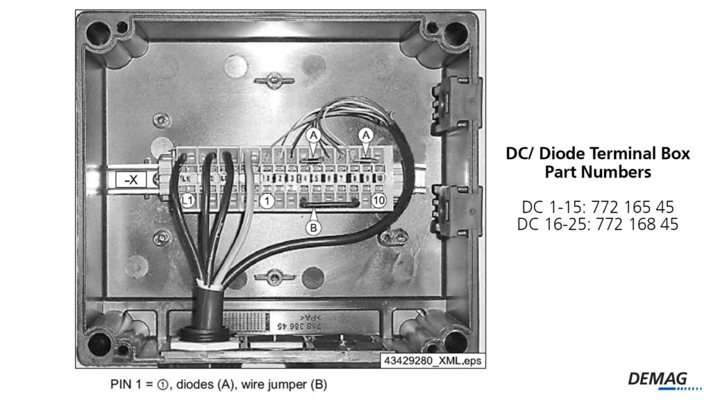
The DC control system requires special 24 vac tri-state signals. A tri-state signal means supplying half wave and full wave signals as inputs to the control board. A critical jumper wire and diodes are added to the terminal strip to generate the tri-state signals and to satisfy the e-stop signal. These tri-state signals carry through the circuit to the DC hoist control board in a multi-conductor cable. The multi-conductor cable is part number 77207345 with an RJ45 connector to plug into the hoist control board. Power is provided to the chain hoist with cable part number 77206845 which also has a mating plug for the chain hoist control board.
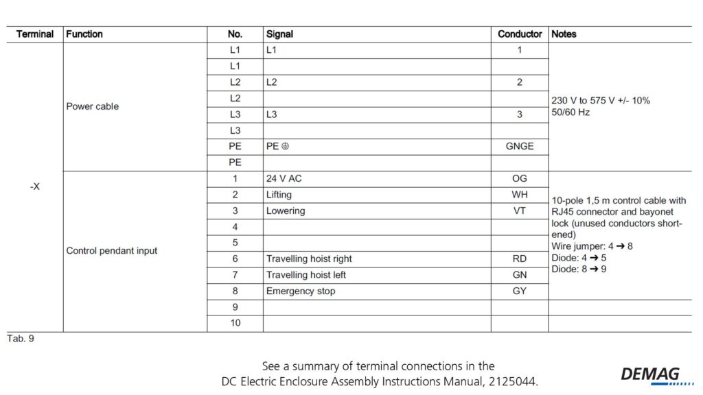
On many occasions we hear from technicians who need advice when the internal wiring of the diode box has been disconnected. We are asked to provide the proper connections for the incoming signals. The incoming signals must be landed on their corresponding input terminals as well as a jumper wire between terminals 4-8 and two added diodes. The diodes are connected between terminals 4 to 5 and another between terminals 8 to 9. The direction of the diodes is important. To have the proper direction, power should be connected to flow from terminal 4 toward 5 and from terminal 8 toward 9. For a summary of the terminal connection, consult the DC Electric Enclosure Assembly Instructions manual, 21125044. Below is an excerpt from this manual for reference.
Always reference the proper documents and manuals. Download the full schematic for the connection by completing the form below. Following this schematic, and manuals, you have full view of the connections needed and you can expect the system to run as intended. Always observe all safety rules when working with electricity and test all functions, including the e-stop, before putting equipment into service.
Don’t forget to reach out to one of our Demag authorized dealers in your area for all your service needs!
Read more about the DC Chain Hoist on the blog!
The Ultimate Guide to Demag DC Chain Hoist Error Codes

- Understanding Wire Rope Lay for Your Next Wire Rope Hoist Repair or Inspection - December 21, 2023
- From Customer to Demag USA Technical Trainer - May 9, 2023
- Diagnosing Additional Error Codes on Demag CANBUS Hoists and Cranes - March 28, 2023